


Reverse Engineering
Reverse Engineering services are used for a number of purposes throughout many industries. Oftentimes manufacturers have an operational part, but lack a model, drawing, and tooling. Reverse engineering is an extremely effective method of producing 3D CAD models or 2D drawings from an existing component. At Made to Measure, we can evaluate and measure every aspect of your component in order to develop the essential drawings & 3D models needed for manufacture.
Using a combination of 3D laser scanning, touch probes, scanning probes, and hand tool measurements, we can readily replicate physical parts with a number digital formats. Scanned data shows the current state of components current state, and often serves as baseline for new product development. Do you need to update old drawings? Were they simply lost to time? Do you need to design all-new tooling from a prototype? When you need to reverse engineer a model or drawing from a part, Made to Measure is ready to provide the metrology solution you need.
Reverse Engineering can help:
- Establish a reliable 3D CAD Model
- Reproduce an outdated or obsolete part or product
- Advance your team’s product or part development
- Investigate design that can be improved or modified
- Innovate an existing part or product design
- Repair obsolete equipment

What is the Reverse Engineering process?
1. Analysis of the Part and Deliverables – Before we provide an estimate for your reverse engineering project, our Metrologists first analyze the intricacies of the component. Upon inspection, our Metrologists will determine if the deliverables required by the customer coincide requirements for output and accuracy. Additionally, the Metrologists review the project deliverables against our capabilities to develop the best possible solution. If the objectives don’t align with our core competencies, the Metrologist will recommend not taking on the project.
2. Capturing Physical Part Data – After we analyze the part, we capture the measurement data needed to create the 3D model utilizing either a CMM-based Nikon laser scanning system or our hand-held Creaform MaxSHOT laser scanner. With these high-data, high-accuracy collection laser scanning devices, we can quickly and reliably collect the data to complete your model in a timely manner.
3. Data Processing and Model Creation – During this stage, we edit, refine, and tailor measurement data for the next step of the Reverse Engineering process. We then prep the data for reverse engineering based on the accuracy and efficiency needed. Lastly, we format measurement data according to the customer’s desired output and preferred reverse engineering process.
4. Final Review – Once complete, our Metrologists verify that the CAD model is accurate to the measured data. A comparison between the measured data and the CAD model is performed using the same color map analysis process that we use for inspection. Once we verify the results, we send the 3D model to the customer so they can begin new product development and manufacturing. With the verified model, we can also provide a 2D fully-dimensioned drawing.

Reverse Engineering with CAD Models
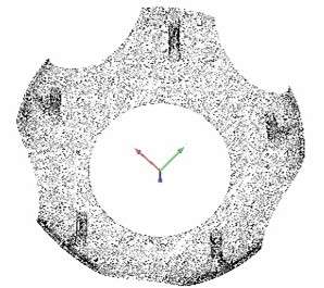
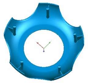
Laser scans produce a point cloud or a polygon mesh which is ideal for reproducing CAD models for tooling, molds, dies, products, and components. 3D Surface Modeling (also known as surfacing) places a surface on your point cloud of data, essentially building a new visual model for your product.
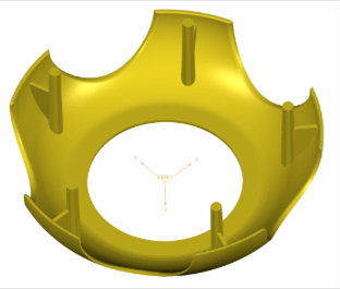
Made to Measure utilizes PTC Creo Parametric (formerly Pro Engineer), Solidworks, and GeoMagic Design-X modeling with conventional surfacing tools, as well as those included with the special Reverse Engineering Extension, to create a three-dimensional, fully-surfaced product on the screen, so you can visualize your product in its entirety. The extension allows our technicians to import point cloud data, transform it into a triangulated mesh model, and subsequently model both free-form and analytic surfaces, using the mesh model as a three-dimensional reference.
Reverse Engineering Services Can Include:
- Updating or creating new 3D CAD Models
- Producing 2D fully-dimensioned drawings
- Generating Surface Models and Parametric Solid Models
- STL file creation
- NURBS file creation
- Color Map analysis and report generation (Part of our Inspection Services)
3D Laser Scanning Services
The 3D laser scanning process for reverse engineering yields outputs in one of several major categories. Each of these derivatives offer unique benefits, and each customer may have different needs. As such, the deliverable is customized to meet their exact requirements. To help you understand the differences in each model and the applications they are best suited for, take a look at the chart below.
| Output | Point Cloud | NURBS Surface Model | Hybrid Model | Direct Model | Class-A Surface Model |
|---|---|---|---|---|---|
| Overview | Raw Data | Exact Model of Surface | Combination of Features & Surface Patches | Feature-Based w/ No Connections | Highest Surface Quality Level |
| Price Level | $ | $$ | $$$ | $$$$ | $$$$$ |
| Key Characteristics | -Raw data as collected from the measurement device -Basic XYZ coordinate data -Minimal data editing performed -Basic building block on which subsequent files are based |
-Captures as-built state -Includes manufacturing defects -Non Class-A surface finish -Static IGES or STEP surface model -Patchwork of small surfaces |
-CAD data converted from scan data -Can ignore or incorporate manufacturing defects -Export IGES (STEP…) surfaces or solid -Modifications require re-trimming |
-Can be used in any CAD system, even feature-based systems -Works with raw geometry -Quicker and easier to combine with other 3D model formats -Easier to rework and modify |
-CAD data converted from scan data -Freeform surfaces of high efficiency and quality -Surfaces have curvature and tangency alignment -G2 or G3 curvature continuity |
| Typical Applications & Notes | -Expert care is needed when dealing with only raw data files | -Captures as-built state (exactly) -Includes manufacturing defects -Patch-work of surfaces -Very good for free form shapes such as hand formed surfaces, artistic elements, and parts difficult to model in standard CAD packages |
-Few modifications to the file are needed -Exchange file format -2D drawings are needed -Surface finish must be smooth |
-Feature-based geometry -Design intent -Simulation -Rapid design change |
-Feature based geometry, design intent -Used when model will be modified -2D drawings are needed -Surface finish must be smooth |
| Common File Types | .stl, .asc, .xyz, .obj | .step | .stp, x_t, .iges | .stl, .step | .stl, .asc, .xyz, .obj |
3D Laser Scanning
3D Laser scanning is a non-contact, non-destructive measurement technology that digitally generates 3D point cloud data, ultimately turning your physical parts/products into a digital representation of the physical object’s exact size. Our CMM-based laser and Portable Scanning Arm systems can capture an abundant amount of precision data(in comparison to some traditional methods).
Our experience in 3D scanning services ranges across a broad spectrum of industries. From Aerospace and Automotive scanning to Medical devices and supplies, we take care of 3D laser scanning parts that require high degrees of accuracy.

Typical applications for quality Laser Scanning:
- Part to Part Comparisons
- Repairing Tools
- Data Archiving of Legacy Parts
- Rapid Prototyping
- First Article Inspection
- Reverse Engineering
- New Part/Product Development
- Part to CAD Comparisons
- Quality Control
Scanning makes measuring complex parts simpler and faster than ever before. By capturing detailed point cloud data through laser scans, we are able to inspect your most intricate parts. 3D laser scanning allows designers and manufacturers to see a visual representation of geometric features and free-form surfaces of their parts/assemblies. With 3D laser scanning services, Made to Measure can help your team resolve issues and make design improvements with detailed feedback.
In-House CMM-Based Laser Scanning
How can 3D scanning help your business? Made to Measure’s CMM-Based 3D Laser Scanning expertise can aid your company in tackling quality bottlenecks, design modification recommendations, and much more.


On-Site Laser Scanning
Need our 3D Laser Scanning services at your company’s facility? We offer 3D measurement for on-site installations, use-case demonstrations, large-scale reverse engineering, and more! We understand the logistic difficulties and additional cost involved when shipping large, heavy, and unique parts. Made to Measure provides On-site Laser Scanning for this very reason! So whenever your projects aren’t as mobile a one of our certified metrologists, we can ship our team to you instead. We’ll come to you and perform the scans, saving you time and unnecessary headaches.
See how on-site laser measurement can help you save on logistics, shipping wait times, costs, and more! Reach out to us today and see how we can work with you to take care of any 3D scanning services you need.


Color Mapping

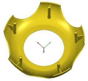
While text-based inspection reports from Coordinate Measuring Machines (CMMs) and Vision Measuring Machines (VMMs) are typically well-suited for most dimensional measurement projects, it’s sometimes more effective to show results graphically with 3D Chromatic Reports, commonly known as “color mapping.” We create easy-to-read Chromatic Reports by scanning your part and comparing the point cloud data to your CAD model. Measurements are given a color to represent how far they are over or under their target. Once a component is scanned, software is utilized to analyze and highlight the differences between the measured part and the nominal CAD model producing a color map. With the part-to-CAD comparison, deviations are represented by colors that illustrate the magnitude of nonconformities to the intended design.
3D color maps, succinctly present the discrepancies between the scanned part and its nominal CAD model. Chromatic Reporting allows your team to easily evaluate the accuracy of your existing parts and prevent fit and functionality issues.
Use Color Mapping for:
- Creating a visual comparison of parts to CAD model
- Highlighting key areas where deviations are occurring
- Identifying missing, added, or mislocated features
- Determining viable part enhancements
- Full Article Inspections (FAI)
- Modifying CAD models to conform to the actual part
- Ensuring that parts meet specifications prior to production


3D Laser Scanning makes measuring complex parts simpler and faster than ever before. By capturing detailed point cloud data through the laser scans, we are able to inspect the most intricate of parts. Get a big picture look at the parts your team is making with our Color Mapping Services. Color Mapping or “Chromatic Maps” allow designers & manufacturers to get a visual perspective of what’s going on with geometric features and free-form surfaces of their parts, components, and assemblies.
Color Mapping Capabilities
Made to Measure utilizes CMM-based Nikon laser scanning systems and a hand-held Creaform HandySCAN Black laser scanner device to capture the data. We then use GeoMagic Control software to create color maps for inspection. We can also incorporate CMM and Vision data to enhance the accuracy of your reports and CT scanning to capture internal features. Additionally, Made to Measure is able to laser scan all material types, has a scanning range from 1mm to 10m and can perform the 3D laser scanning either onsite or at our facility.
- Scanning via Nikon L100 Laser Scanning System, Nikon LC15DX Laser Scanning System, or Creaform HandySCAN Black Elite Laser Scanner
- Merge CMM, Vision Systems, and CT Scanning data for an enhanced report
- Ability to laser scan all types of material and components sizes from 1mm to 10m
- Services performed at your facility or at Made to Measure


Computed Tomography (CT Scanning)
An Inside Look

Industrial Computed Tomography (CT) Scanning drives high-powered X-Rays through the material of a part to construct digital images. The digital images, sometimes known as “slices”, are then turned into a 3D Point Cloud to utilize the image results for analysis. This non-destructive testing approach to metrology paired with our experienced Metrologists takes dimensional inspection to a whole new level! Taking into consideration that the whole part is digitized, the chances of overlooking important measurements is highly reduced. In addition, pre-production time is cut down tremendously due to the omission of sectioning and the elimination of the need for complex fixtures.
With CT Scanners you can:
- Get a First Article Inspection (FAI)
- Measure hard to see/internal features without sectioning
- Compare parts-to-parts or parts-to-CAD models
- Identify defective parts and structural flaws
- Evaluate your suppliers line of production
- Reverse Engineer existing parts or components
- Analyze Wall Thickness for structural or pressure conditions
Modeling
3D Surface Modeling
Laser scans produce point clouds or polymesh. While these .stl and/or .asc files are great to pull out specific points, you cannot reproduce a mold, create a cutter path, or make any adjustments to the file from these. That’s where 3D Surface Modeling (also known as surfacing) comes into play. It places a surface on your point cloud of data, essentially building a new visual model for your product.
Made to Measure utilizes PTC Creo Parametric (formerly Pro Engineer) modeling with conventional surfacing tools, as well as those included with the special Reverse Engineering Extension, to create a three-dimensional, fully-surfaced product on the screen, so you can visualize your product in its entirety. The extension allows our technicians to import point cloud data, transform it into a triangulated mesh model, and subsequently model both free-form and analytic surfaces, using the mesh model as a three-dimensional reference.
CAD Deviation Analysis
Deviation analysis (also known as color deviation analysis) is used to verify the integrity of the modeled data with reference to the mesh model, ensuring that all information and reproductions are accurate.
We can create a digital image of your physical product via laser scanning (in excess of one million points). Aligning the points to the original CAD model, we are able to determine the distance between each digital point to its closest surface. The area of that surface is then colored by the analysis software, according to the magnitude of the deviation. The data can also be used to create .stl, .stp, and/or .igs files.
Increasing your production line’s accuracy and efficiency starts with quality measurements and that’s where CAD Deviation Analysis comes into play.
Request a quote for your next project!
"We manufacture aftermarket turbine engine aerospace parts. We not only use our CMMs for inspecting the very tight tolerance that we have to produce with our parts, but we also rely on them to reverse engineer OEM parts to manufacture. The AUKOM training we received at Made to Measure has helped our engineering staff understand how to get the correct results from our CMM for what we are trying to achieve. The training has also helped our quality staff understand how to inspect and evaluate results properly to meet the requirements of the print. The staff at Made to Measure are extremely knowledgeable and the training was very well presented."
Bryan S. Aerospace Parts Manufacturer, AUKOM Level 1 Certified
“I couldn’t be happier with [Made to Measure]. They do great work for us.”
Sr., Molding Engineer, Commscope
“Learning the different ways that a CMM evaluates features on a part; least squares, minimum zone, max inscribed, and min circumscribed; and when to use which evaluation, has made a huge difference in the accuracy of our CMM programs after going through the AUKOM courses . Our CMM programs are now much more repeatable between users and even locations across the globe (China)”
Joe B. QA Supervisor, Gear & Engineering Corp.
"Thank you for the fine and fast work of all involved at Made to Measure to create this cap model. The model helped us create a new model and reproduce a new mold that is now producing parts locally."
J.H. Engineering Manager, Zeller Plastics
“We used to do everything in-house….but now that we‘re getting skinnied down to the point where you don’t have time to do it, we sought an outside service bureau. I couldn’t be happier with Made to Measure. They do great work for us.”
J.M., Sr. Molding Engineer
“Has anyone told you guys you’re awesome lately? The Made to Measure team makes it a pleasurable business experience.”
Christine R., Division Supplier Development
"You guys do great work. I’m glad I can recommend one of our good customers to you"
Local Tool & Die Manufacturer